

Tesoro
-
Posts
26 -
Joined
-
Last visited
Content Type
Profiles
Forums
Events
Gallery
Store
Posts posted by Tesoro
-
-
4 hours ago, Cody191 said:
I would like to thank you all for all this information. I had been preparing to buy a couple new mag 10’s this year. Between this thread and a couple others you presaged me some headaches. Just placed order for 2 magnum metalz
Dont get scared away from cannons! there are always 'a' models in all brands and atleast the ones I posted about and some others had weak controller boards. They have since been re-designed. The diff between cannon and other small companies is cannon will still be in biz after the next recession. ( coming to a theater near you soon) -
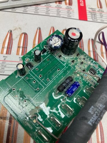
I recd my relays yesterday and anxiously soldered them in (correctly using paste). GONG. still dont work!! the up relay makes the same click sound but no power to motor! I have a good board which I put in to check that motor works in both polarities. So after all that back to square one. I examined the board with a loupe and see no visible damage/burn spots. So I give up and have ordered a couple of the new boards that have wire mods for the pre 2010 version.
If I were to keep the riggers I would modify them to use the scotty auto stop and get rid of the board. with some mods the autostop could be mounted in the ball hanger threaded hole.
-
 1
1
-
-
I think my problem was I ran a 10 ga wire to a terminal block for some pumps and then connected rigger to the block. I think I prob lost some conduction in the terminals and that, combined with some corrosion on my female cannon plug, caused issues with a heavy ball. I have since ran a dedicated 12ga wire from battery to the plug.
I have bought new cannons and will be selling my mag10ts's once I have them back in shape. if I were to keep them I would look at finding a heavier duty relay that would fit or modifying the board to make them fit. However I am sure that they would work fine stock with good power supply. when I get my new mag5 the first thing I will do is take a board out and see whats up with it. I bet the relays are much larger.
I have had both canon and scotty and I will take the cannons any day for many reasons. we need to treat our computer conrtolled cannons like we do our plotters and make sure they get good power.
-
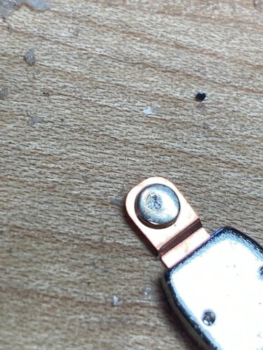
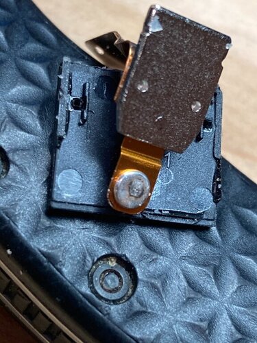
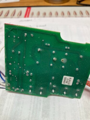
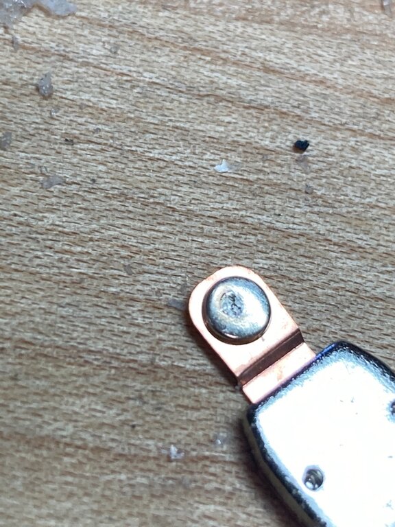
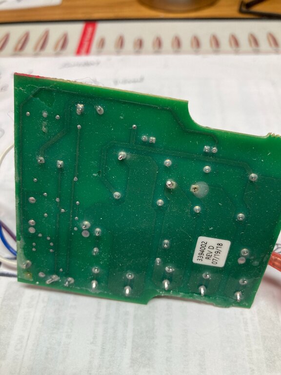
I decided to repair a couple of the bad boards I have with burned out 'up' relays. Those are the ones to the outside of the board. The inner one is the down.
Ordered a $20 soldering kit and worked well. The trick is to solder a blob on the pins and then heat up the blob and use the solder sucker as it will heat the original solder to melting as it dosent melt easy. And then can use a piece of wick to pick up any scraps. the relays wont fall out and have to use a box cutter blade to pry relay and then heat the pins to loosen the last bits of solder. patience, pita and took about 1/2 hr per board but got all 4 relays out with no damage. installing the new ones will be a 5 min job when they arrive.. just a fyi incase.
I took the relays apart and the contacts were a bit fried looking. assume this is the prob.
I bought 3 boards from cannon last summer and it looks like the relays were repaired as the solder job was real amateur.
I think my relays burned from 18lb balls and not sufficient amperage due to wiring. all that is fixed now.
-
3
-
-
Thx, I have 2 5’s coming! All I need.
-
just looked. same motor part no. for mag 5 and 10.
-
Heck this is getting cheaper everytime I look. I have the canon ss swivel bases and I never use the extensions so the 5t is all I need.
ps: have to look at how easy it would be to swap spools with the short stop wire attached to the spool.
-
Yeah thanks I just finished comparing parts on schematic to double check. same drive gears etc. So paying quite a bit extra for white and a ss spool ! probably more for the people who color coordinate their gear with the boat!
The new version is pretty neat because you can buy a spare spool for 40 bucks. load it up, and swap out at sea incase of a major snafu.
-
I am in scotty country so thats why I am posting here. I have 2 mag10ts and messing with the bad boards right now. I will get them working one way or the other. However I want to buy 2 new ones. I like the mag10 power etc and am looking at 2 new TS or just the regular mag10. Does anyone know if there is any difference to them other than white paint and a ss spool? I could care less about the color and assume that the composite spool works just fine. the 200 dollar difference is significant like 400 bucks less for a pair!
-
I posted the pic of the board with bad soldering. I have another one where one of the pins is smoked/burned. I just ordered a bag of relays - 20 order minimum and a better solder gun/solder sucker. I already have wick. Will do my best to replace the relays. I dont want to bypass and cancel out the short stop. I can see accidents happening.
I also borrowed a scotty and took their autostop off to see if I could adapt it to work on my scottys. I think I could get it done but the turn switch/button would be in a bit of an awkward position.
-
like this??!!l
-
Scotties are sounding better all the time. Scotty would never leave their customers high and dry by cancelling production of problematic parts in not so old units. I guess thats the diff when a long time established company makes products with lifetime warranty.
-
makes sense. and then the up/down switch is integrated into the board via the relayss? get rid of the board and you need to be 'on the ball' for retrieve! I am looking forward to getting mine fixed properly with the new boards and selling them!
-
My Mag10 ts are 2010 and have 20a relays. I dont even know what this board does! I would love to be able to get rid of it. s
-
what a PITA!! but at least you found it.
I have 3 burned out boards. One board I got last summer from canon directly did not work. I called and the guy sort of made a slip and told me it must have been from one of the bad batches they got from china. he sent me a replacement that worked...for a while. I dont know jack about electronics but did look up relays and they burn out when shorted. so who knows.
And then I found this!!!!!
https://www.mikesreelrepair.com/cannon-050175-3394006-modified/
-
is there a reason why you need to replace the relay coil? I assume that is the tubular thing that sticks up away from the board?
-
Yikes that work is above my pay grade! but thanks. if you get it figured out I know a guy who fixes boards and who does micro soldering. Sent him a board out of my macbook that got water damage and he replaced the 10cent part that made it inoperable.
-
Hi I am out in Oregon. I use mag 10 ts and we are right in last week of salmon season and my up switch quit on one rigger yesterday. Of course with 15# ball 150 ft deep! I could not figure out how the tool worked - might have been for a diff cannon that was on boat before. I hand pulled it up.
I just put a new board in that one a month ago. One of the relays was cooked. I found relays at supply place for a couple of bucks each. interested to find out about the socket idea for easy replacement.
taking my rigger apart this morning to see what happened. I have good wiring and just redid it so who knows. But I did blow a fuse 2x on that rigger over the last 4 weeks. 30amp but they looked like cheap opaque fuses. put in good quality one and nothing since then.
I have a spare board and if switch bad ( doubtful) can get one at napa.
-
Thanks. Should have specified 1992+ V2 hull only.
-
Yes I saw that one thanks but corrosion is always the issue with 15+ yr old engines and electrical when run in and around the salt. they all look good in low res sales pics... Thats why I like fresh water boats if they are slightly vintage! I also will take an ox66 any day over a 4 stroke. But thats me.
-
yeah thats going to be too much weight for me...great boat though. . the 22 ft size will be my best compromise for trailering and handling siglehanded. Thanks
-
That would be my ideal size but I sold my cummins 4x4 3/4 ton n bought a 1500 diesel. I pull my 6500 pound camper okay n its hilly here.
ever put that on the scales?
-
Nice but for sake of my wife need cuddy for bathroom privacy when others on board
-


Cannon mag 10 STX stopped working
in This Old Boat
Posted
thx for the advice but I give up! I must have damaged in the inner core or who knows what but to r/r the relays for a second time is not wise. I am just getting the new version boards that have been re-wired for plug n play with the old mag10's. should have done that from the start but wanted to try for the fun of it.